 B. Multimeter
In our experiments we will need to measure resistance, capacitance, voltage, and current. We will be using a digital mutlimeter for this. Here we describe how to use a mutlimeter, and what setup is required for each of the different measurements. Mutlimeters come in all kinds of forms: analog and digital, cheap and expensive, but their usage is all very similar. If you know how to use one, you know how to use all of them.
.
Digitial Multimeter
If we look at any digital multimeter, two things are noticable immediately: the display with big digits and the round dial with all kinds of different settings. In addition there are two cables, one black and one red, with pointed ends, the multimeters test leads. Most multimeters have a fuse, that protects them in case they are used in the wrong way. Hence, when your multimeter doesn't seem to work anymore, don't throw it away: most of the time, all you need to do is replace the fuse, which costs only a couple of cents.
Also, most multimeters have only one way to connect the black cable, but there are several plugs for the red cable. You want to avoid the plugs that say "A" or "mA" (for ampere, that is current) on them, because those are the ones that cause trouble (more below). Hence, it is a good habbit, if not sure, to connect the plug that says volts or ohms.
Another thing to notice, especially with our multimeter, that by default it tries to measure AC. But we are only doing DC. So, if you measure the voltage of a 1.5 volt battery, and it does not read around 1.5 volts, but something more like 0, then it is not because your multmeter is broken, but because you have it in the AC setting. Simply switch it to the DC setting by pressing the DC/AC button.
.
.
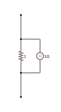
 measuring resistance |
Resistance
Measuring resistance is the easiest: first, you need to turn on the multimeter, most of the time by simply turning the dial. Second, you set the dial to the resistance setting, usually indicated by an Omega for Ohm. Here you start with the highest possible setting, usually some mega-ohm, like 100M. Then you simple take the two pointed leads and connect them to the resistor you want to measure. Make sure the resistor is not connected to anything else. This is very important.

Let's say the resistor you want to measure is some kilo-ohms. Then if you measure it with the mega-ohm setting we selected first, it will read all zeros. Because compared to mega-ohms, kilo-ohms is basically nothing. So what you do then, you gradually adjust the dial, wait a little for the reading to stabilize, and continue this process until your reading starts to make sense. Now if you have something that has no resistance, either because it has none (like a wire or a superconductor), or because it has a short circuit, then continuing this process to the lowest setting of your device, it will always read zero. If it does that, then you know you have a short circuit.
.
Short Circuit
We can measure the resistance of just one component, like a resistor, or we can measure the resistance of a whole circuit. So before we connect the battery to our circuit, we can connect our multimeter instead of the battery. If the resistance we measure is zero, then our circuit contains a short. That means our circuit is a short circuit, and we should not connect the battery. Instead we should find the short, fix it, make sure it is fixed, by again measuring the resistance of the whole circuit. Only after being certain that we do not have a short, should we connect the battery!
.
Capacitance
Measuring capacitance is completely analoguous to resistance. You set your multimeter to the highest capacitance setting it has, usually indicated by a C for capacitance or something like nF for nano-Farad, or uF for micro-Farad. Again start with the highest setting. Then connect the capacitor to your multimeter.
A couple of remarks on measuring capacitance: first, not all multimeters can measure capacitance. Actually most of the cheaper ones, can not measure capacitance. Second, when measuring capacitance, you should do this only for the small capacitors that we have. Large capacitors (like the ones inside washing machines) are very dangerous. Quite often they might be still be charged, and a shock from a large capacitor, that was connected to 220 volts, and still holds some rest-charge, could be lethal!
.
 measuring voltage |
Voltage
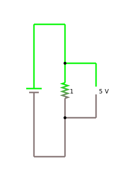
Measuring voltage is a little more complicated: you measure voltage while your circuit is connected to the battery, that is on a "live" circuit. When measuring anything on a live circuit, one has to be quite careful not to accidentally cause a short circuit. So make sure you only touch the pieces you intend to touch! The diagram on the side depicts how you measure voltage.

First, you select whether you want to measure DC or AC type voltage. We will only measure DC, hence select the DC setting. Second, pick the voltage setting that is slightly higher then your batteries voltage. So if you have a 9 volt battery, select the 10V or 20V setting on your multimeter. Finally, connect the black lead first, usually on the side of the resistor that is connected to the negative pole of the battery, and then connect the red lead to the other side of the resistor, usually the one that is connected to the positive pole of the battery. If you happen to switch the poles, you will get a negative reading for the voltage. That is fine.
.
 measuring current |
Current
Measuring current is the most complicated, and should be done with care. Many multimeter (or better fuses) have not survived a wrong current measurement! The reason being, when measuring current, actually current is flowing through your multimeter, and to much current is just deadly for anything. But that is what fuses are for: in your multimeter, they protect the multimeter, in your house, they protect you.
For most multimeters, you will have to not only change the dial setting to measuring current (A), but you also have to reconnect the red (positive) lead to a different output terminal. Most multimeters actually have two different one: one for lots of current, like 10 amperes (10A), and one for smaller currents like milliamperes (mA). We only work with batteries, so the milliampere setting is what we want. Again, we start with the highest values our multimeter allows for, maybe something like 500mA. And we need to tell it, if we intend to measure DC or AC: we will only measure DC, hence select the DC setting.
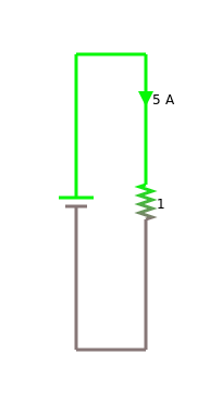
Next we connect the multimeter to our circuit. If you look at the circuit for measuring current on the side, you will notice, that the multimeter is part of the circuit. So we kind of have to "break" our circuit: we need to find a spot where we can integrate our multimeter into the circuit. The easiest way to do this, simply remove one of the connecting wires, and replace it by the multimeter.
.
Transistors
Some modern digital multimeters actually allow for the checking of transistors and diodes. They can check if the transistor is still working, if it is a npn- or pnp-type, and usually can measure the transistors hFE value. For the details on how to do this, you should check your multimeters manual.
.
Inductance
Measuring inductance is exactly like measuring resistance or capacitance. However, only few multimeters can measure inductance.
.
References
[1] Multimeter, https://en.wikipedia.org/wiki/Multimeter
[2] Multi-meters current, isaac.exploratorium.edu/~pauld/summer_institute/summer_day15current/meters_current.html
.